GPD MicroPC: Adding battery charge control by leveraging the charge controller’s overtemperature safety feature.
(A Reddit thread for discussion of this project is here.)
The GPD MicroPC (archived page) is a tiny laptop (ca. 153 mm x 114 mm x 21 or 27 mm) with an 6 inch 720x1280 screen and a lot of connectors (3x USB A 3.0, 1x USB C with display port alt mode and which acts as power supply input, 1x HDMI, 1x Ethernet, 1x RS232, microSD, audio/microphone jack). It comes in two variants: An older variant with an Intel Celeron N4100 CPU and a revised variant with an Intel Celeron N4120 CPU. It has 8 GiB of RAM and a M.2 slot for SSDs (SATA protocol only) (it accepts by default only 2242-sized M.2 SSDs, but it can be modded to accept the more common 2280 size).
A general discussion forum for this device is for example at reddit.com/r/gpdmicropc.

The GPD MicroPC. (This photograph is not taken by myself.)
The hardware is pretty standard hardware, and so it works without problems with Linux.
Although the laptop serves as my primary computer since somewhen 2019, it has a few annoying issues. One issue is that the internal battery does always charge to 100% when connected to power, no charge control is possible. Having the LiIon battery always sitting at 100% decreases battery life, and a couple of people also have reported that their batteries became swollen after some time.
This was annoying me already from the beginning, now I finally did add a hardware based option to manually inhibit charging.
Recently (March 2022) I discovered that my battery was swollen, so I decided to discharge the cells and discard them and replace them with new cells. After disassembling the battery pack, I took the chance to study the pack’s electronics board and found out that it uses a Texas Instruments “TI BQ40Z50” charge controller. Reading the datasheet and technical reference manual, I found out that the chip has under temperature and over temperature safeguard options (a few programmable temperature ranges) which can be programmed to limit charge current or totally stop charging and/ or output power below or above a certain temperature. The battery pack has one temperature sensor which is attached to one of the cells, and according to the datasheet of the BQ40Z50, the temperature sensor is an NTC (i.e. a temperature dependent resistor whose resistance drops at increasing temperatures) with a nominal resistance of 10 kOhm connected between a measurement pin and ground, and internally the chip applies a 18 kOhm pull-up resistor to the measurement pin when performing temperature measurement.

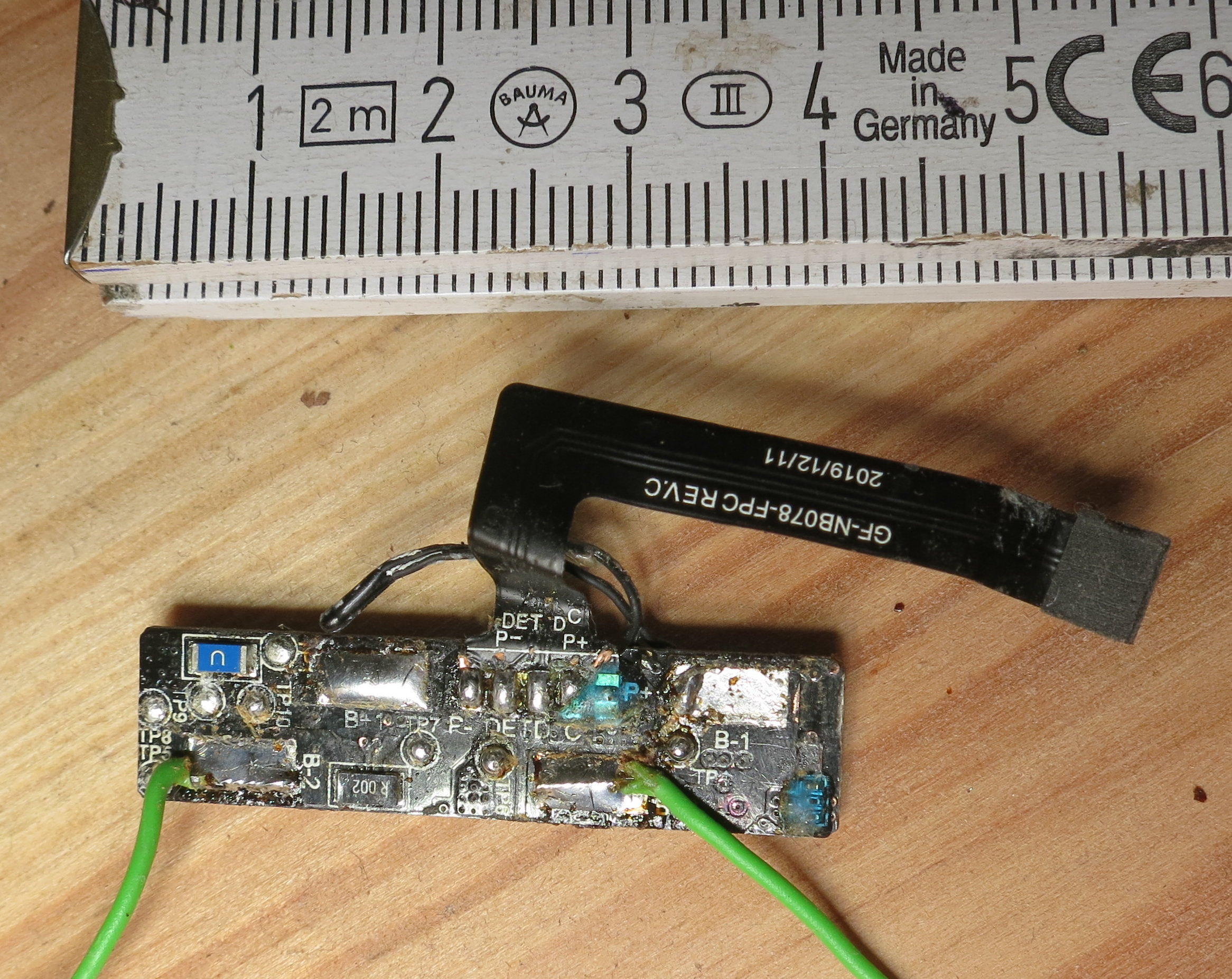
The battery pack’s electronics board. The temperature sensor is the small black bulb at the end of the two black wires.
I was tempted to explore possibilities to add charge inhibition before I was about to reassemble the battery pack and close up the laptop again.
The BQ40Z50 communicates with the host system via SMBus, and it might be possible to program it also via SMBus in a way to also make it stop charging. But I am not familiar with SMBus and I had no clear sign that from within the laptop’s operating system the SMBus interface was directly accessible (maybe it is, I have no knowledge in that matter).
Idea-wise, simplest mechanical solution would be to add a mechanical switch into the battery cell’s power lines which directly cuts off the cells. This did not seem feasible for it would need three quite thick wires going through the laptop and a larger switch, where was just nowhere the space. Also, when switched off, the battery would also not be able to power the laptop in case of power supply disconnect. And lastly, it seemed a bit complicated mechanics-wise.
Other idea was to intercept the DET-wire of the battery packs connector. My guess is that it connects to the /PRES PIN of the BQ40Z50 (this is to make the BQ40Z50 detect if it is connected to a system, and cut off power if not), making the BQ40Z50 to switch off the battery if /PRES is not pulled to low. I also ruled it out as non-feasible, since it was not easy to intercept (would need to desolder the whole connector ribbon cable and would take too much space and/ or sloppy wired connections to reconnect it). And also this solution would cut off power from the battery to the computer as well.
Then I was thinking about the temperature sensor and the under and over temperature protection feature of the BQ40Z50. Maybe it was possible to make the BQ40Z50 think that the battery was too cold or too hot so that the BQ40Z50 would stop charging? I explored the idea and it turned out that this became a working solution, needing just one thin extra wire attached to the battery pack, a small switch together with a resistor added to the laptop, and another wire to some random ground pad.
I cleared the plastic drops which were on top of the temperature sensor’s soldering spots and measured which of the spot was attached to ground (thereby also confirming that it indeed was connected to ground at one side). The other one then seemed to be the “hot pin”, used for measurement. I soldered a thin wire to it.
Then I reassembled the battery pack with new cells properly (with my modification to make space for an 2280-SSD, but that is another project).

The battery pack, with an extra wire that connects to the temperature sensor.
My plan was now to first drive that wire at different voltages and see what happens. In order to do so, I decided to take from an USB port GND and 5V, add a potentiometer (R2, 1 kOhm, choosen to be one order of magnitute smaller than the temperature sensor and pull up resistor) between GND and 5V, and a safety resistor (R3, 100 Ohm) at the potentiometer’s output, and attach there the “extra wire” from the battery pack. For mechanical stability of my test setup – I definitely did not want to cause any short circuit due wires which could get loose – I built a small circuit board with those components and attached an USB cable to it.


My test setup. The precision trimmer R4 was only added later.
Then I placed the battery into the laptop, looped a USB voltage-and-current-meter into the laptop’s power supply cable, and powered the laptop on. I did boot into my operating system to read out the charging state and power as reported by the battery to the laptop’s firmware and from there to the operating system. I checked the battery state: A few percent, charging. So I had enough time left until fully charged to test potential charging inhibition.
I plugged the USB cable of my small test board into an USB port of my laptop, and then operated the potentiometer, thereby both observing the screen output of the battery charge state as well as the power consumption reported by the USB power meter. Since the temperature sensor is an NTC (according to the datasheet, I have not measured that) connected to ground, turning the potentiometer to the 0 V side would simulate higher temperatures, turning it to the 5 V side would simulate lower temperatures.
I noticed that when the potentiometer R2 was turned to (almost) 0 V or to (almost) 5 V, charging stopped: I could see the power reading on screen to be 0, and I could see a drop of current flow in the USB power meter. This was a first success, showing that I could stop charging by manipulating the temperature reading. I also noticed that there was a small hysteresis when charging would resume: I had to turn it back a bit more to make charging resume. I also got the impression that there is some time factor: Charging would not stop immediately but with a small (few seconds, sometimes(?)) delay.
I first drove the battery controller to think there was an under temperature condition (i.e. turning the potentiometer to the 5 V side), since as I understood LiIon physics from a very quick overview-reading at under temperature charging should not be performed (or only at low current), but discharging would be OK (I might be wrong). Then I tested if power would still be supplied to the laptop by turning off the power supply, and – *pop* – the laptop went off immediately. So, that was only half the desired solution so far, the battery was completely cut off, also not providing power, when in under temperature condition.
Further tests I then made without booting to my operating system, but staying in my bootloader’s screen. The charge status I could read from my USB power meter, having confirmed from the previous run that indeed charging seems to be completely inhibited (and not just lowered) and now knowing what roughly is the power meter’s reading for only operating the laptop without charging the battery.
To get more fine grained control, I added a precision adjustable resistor (R4, 10 kOhm) to the output of my test board and then performed the tests with the potentiometer R2 either fully at GND or fully at 5 V, which effectively means that I just had an adjustable resistor between the temperature measurement pin of the BQ40Z50 and GND or 5 V, respectively.
With the precision resistor R4 I found out that the BQ40Z50’s under- and over temperature safety feature seems to have some hysteresis. I found a setting where (at room temperature) charging is reliably inhibited but power is still provided to the laptop. This was in the “over temperature” range, meaning a parallel resistor to ground. This is desirable, since 1. the NTC is also connencted to ground and so it saves on idle battery consumption, and 2. it is safe for real over temperature conditions.
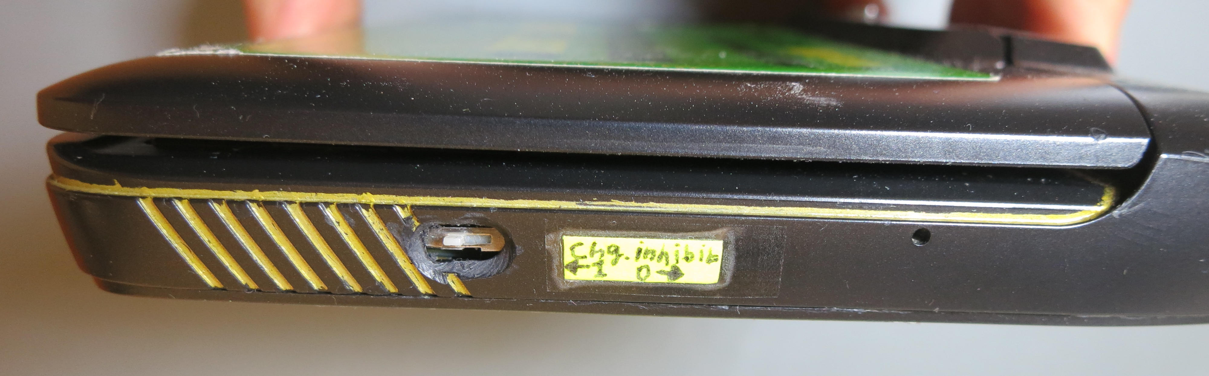
I measured the resistance I found to be around 5.8 kOhm, and so I chose a small 5.6 kOhm resistor I still had lying around. I made a small circuit board for the switch I have already selected and the resistor and cut it in shape to fit smoothly; I selected the free space between the battery and the casing to hold my board. I added the switch and the resistor, and I made an opening for the switch into the MicroPC’s case. The switch I secured additionally with epoxy glue to the circuit board. The MicroPC also had a screw (probably for holding the keyboard, I did not check) at the right spot which I could replace with a longer one to secure my board.


The circuit board with the charge inhibit switch.
Soldering the GND wire from the switch to a wide ground solder pad near the RS232 port, adding the battery & soldering the extra wire from the battery to the resistor, then adding the SSD the setup was ready for testing. And, voilá!, it worked as intended: With the switch I could control normal operation and charge inhibition.
# /usr/local/bin/batt
-- Battery: (values with '(*)' can be changed by user, see option '-h'): --
Present:              1
Remaining:            22%                  charging (Normal)
Status:               Charging
Cycles:               0
Voltage:              7.60/---             Now/Min_Design (V)
Power:                +0                   Now (W)
Energy:               3.47/15.11 (23.56, 64%)  Now/Last_Full (Full_Design, Aging_Leftover) (Wh)
Alarm level (*):      .720                 Wh

-- Charger --
Online?:              1
The output of battery charge state with inhibited charging. Note the “0” in the “Power” entry.


Putting things together.
I then closed the laptop’s case, added a label beside my new switch, and now I finally have the possibility for charge control.


The GPD MicroPC with the freshly added switch for manual charge control.
So, this setup enables to control battery charging in GPD MicroPC by simulating an over temperature condition to the charge controller by adding a 5k6 parallel resistor to the temperature measurement NTC. With a switch this can be switched on and off. The charge controller has different over temperature conditions; the condition that is simulated here stops charging, but does not cut off power from the battery to the laptop. More severe over temperature condition would cut off the power completely.
This solution comes with minimal interference (only one thin wire is needed from the battery, and another thin wire needed from ground on the mainboard) and is quite simple. The NTC is still there and operating. This could lead to different behaviour at different real device/battery temperatures:
I also have observed that while in charge inhibition mode, sometimes the charge percentage climbs up by a few percent. I have to observe further to see if it really is some residual charging, if it is still the settling down phase after connecting new (probably not yet balanced) cells to the charge controller, if it is the charge controller from time to time going out of overtemperature condition, or something else.
If there is to find any free GPIO pin in the MicroPC, charge control could be made software controlled and thus automatic (well, as long as the operating system functions …) by adding a MOSFET for the switch and having that be controlled by the GPIO pin, and a software monitoring charge state and driving the GPIO pin.
The issue of temperature dependent functioning of charge inhibit could, in a next iteration of such a hack, be adressed by
Only perform such work when you know what you are doing and have some electronics and good soldering proficiency. It is very easy to destroy your battery or even your computer, and risk of fire if you mechanically damage or short circuit or in any other wise mistreat the battery cells or damage the battery electronics board.
I take no responsibility whatsoever for what you do. On this website, I only documented what I did to my very own device. This is not an instruction for others to follow.