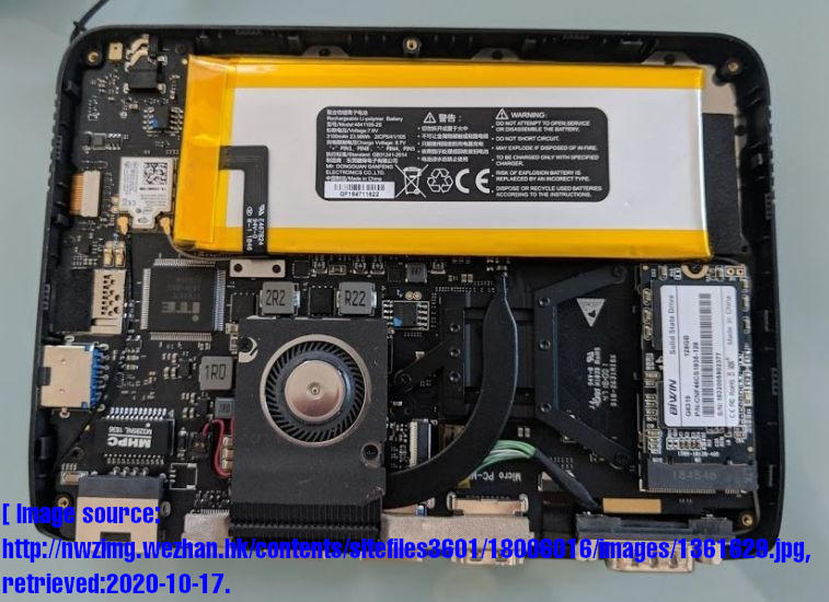
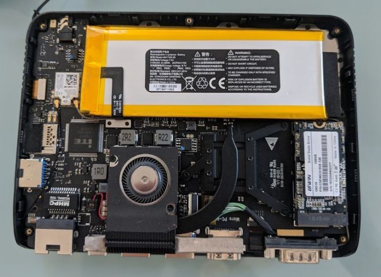
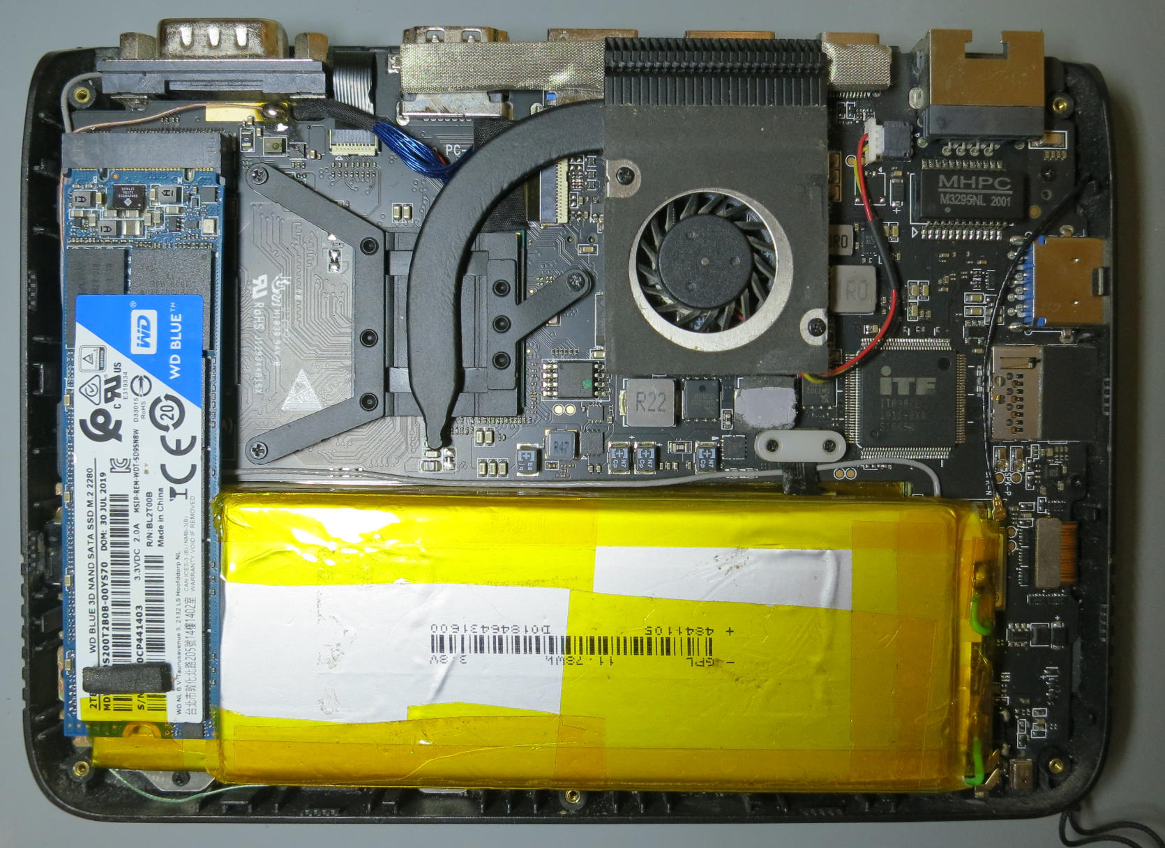
.DSS 2.M 0822 a rof ecaps gnikaM :CPorciM DPG <- gnikcaH <- ed.hcurbnettek.scilef :ereh era uoY

GPD MicroPC: Making space for a 2280 M.2 SSD: Displacing the battery.

(For a discussion: See here on reddit.com.)

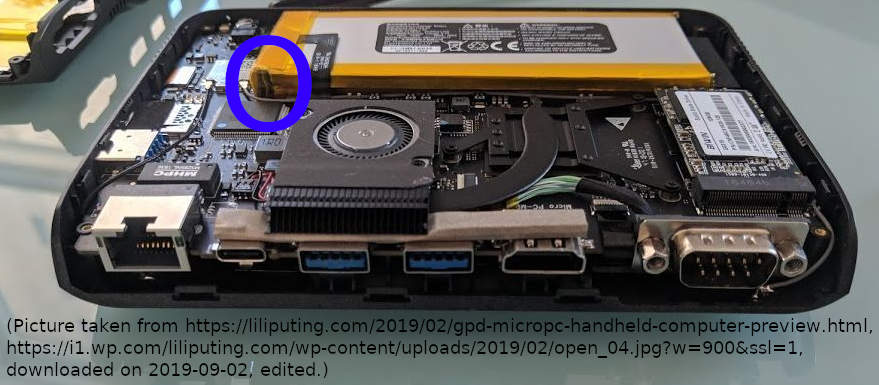
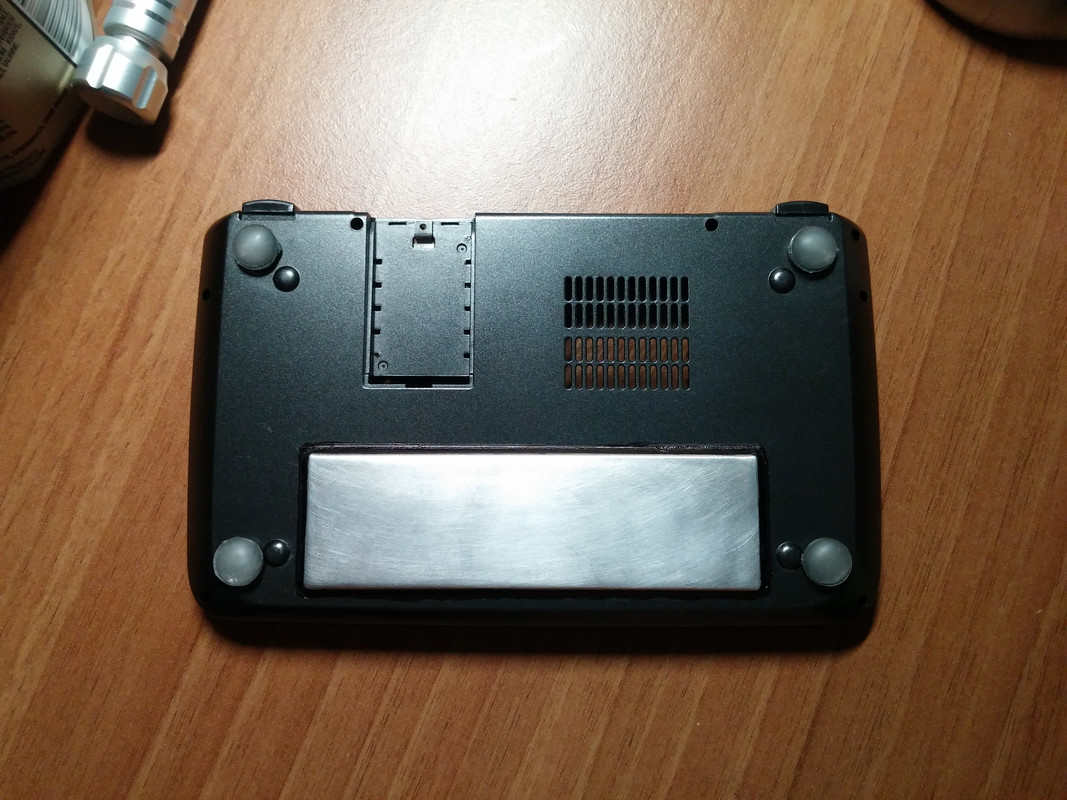
Implementing my plan to fit in an 2280 M.2 SSD in my GPD MicroPC (a 6" x86-64 laptop with loads of connectors), I tried to make space by moving one battery cell.

Before:

GPD MicroPC internals (original), there is only space for a 2242 M.2 SSD. (Image source: gpd.hk.)
(Image source: GPD, nwzimg.wezhan.hk/contents/sitefiles3601/18006016/images/1361629.jpg, linked from gpd.hk/newsinfo/204174.html, retrieved:‌ 2020-10-17. This image is not by myself.)

After:

GPD MicroPC internals, displaced battery makes space for 2280 M.2 SSD. (Image source: Myself.)
(Image source: Myself.)

Originally, there is only space for a 2242 M.2 SSD (42 mm long), and is very difficult to find SSDs in that form factor above 512 GB (as of mid 2020, only un-trustworthy no-name manufacturers supply storage size up to 1 TB).

The most common form factor for M.2 SSDs is 2280, these are 80 mm long. But they cannot fit in in the GPD MicroPC because the battery is in the way.

Two possible modifications came into mind to make them fit in:

  1. Using an extender cable and cutting out a hole in the bottom of the case to fit it there, similar as this example with the GPD Win (discussion: here),
    GPD Win: 2280 M.2 SSD fit in by adding it as a bulge on the bottom. (Image source: reddit.com/r/gpdwin/comments/9229qf.)
    (Image source: Reddit user “Hunam_”, s8.postimg.cc/i8fkmz011/20180812_173002.jpg, linked from reddit.com/r/gpdwin/comments/9229qf, retrieved:‌ 2020-10-17. This image is not by myself.)
  2. displacing the battery to make space for a longer SSD in it's original space.
    This approach was choosen by me and is described below.

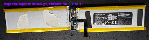
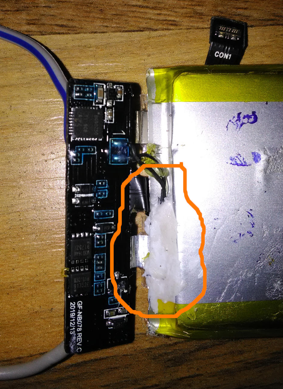
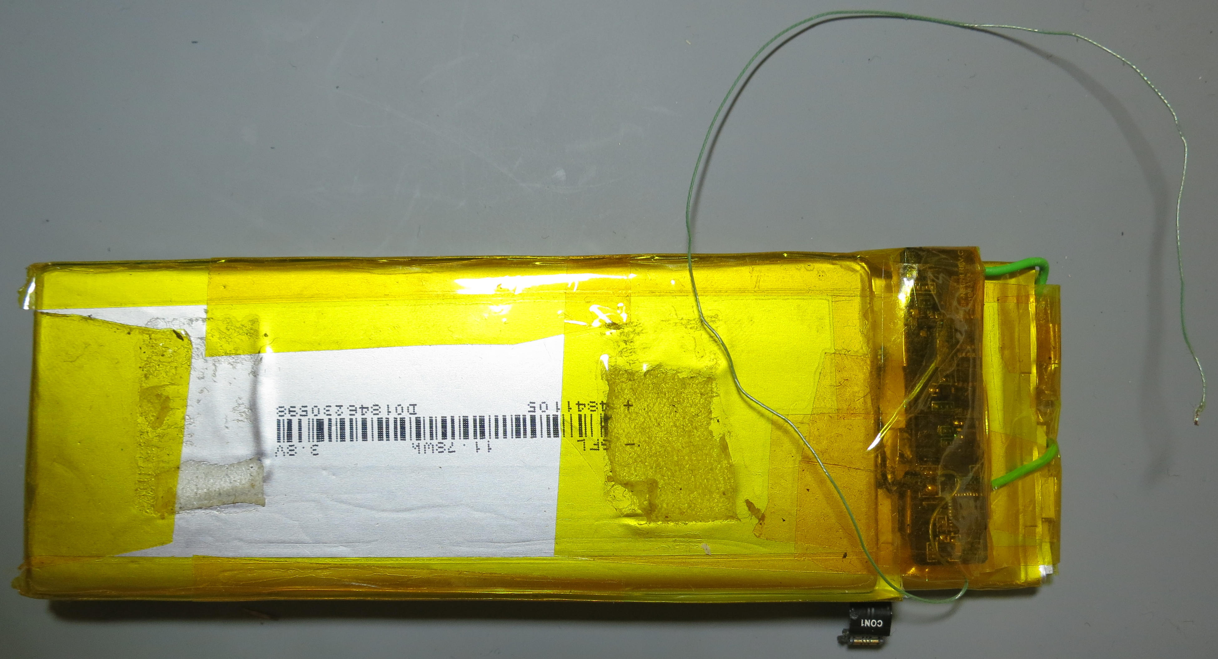
The battery consists of two cells, attached to each other with double side adhesive tape, and soldered to a small electronics board. Each cell has a nominal voltage of 3.8 V, making a battery pack with a nominal voltage of 7.6 V.

The work was carried out with a battery which was almost discharged to reduce the risk of fire in case of accidental mistreatment. During all solderings extreme care was taken to not create short circuits.

First, the single cells had to be detached mechanically. Because the adhesive tape was too strong to simply pull them apart without the risk of mechanically damaging them, a credit-card sized bank card was used, like a blunt knife, to go in between the cells and slowly push away the adhesive and little by little get the cells apart.
In a repetition of that work later I had besser success with a real knife, taking care not to damage the cell.

Then, the top cell had to be moved to the left, to make space for the longer SSD. Because the battery's electronics board then would not have space anymore (it cannot be moved far since it has a short connector cable to the main board), the lower cell had to be moved to the right so that the board can sit under the top cell close to it's original position.

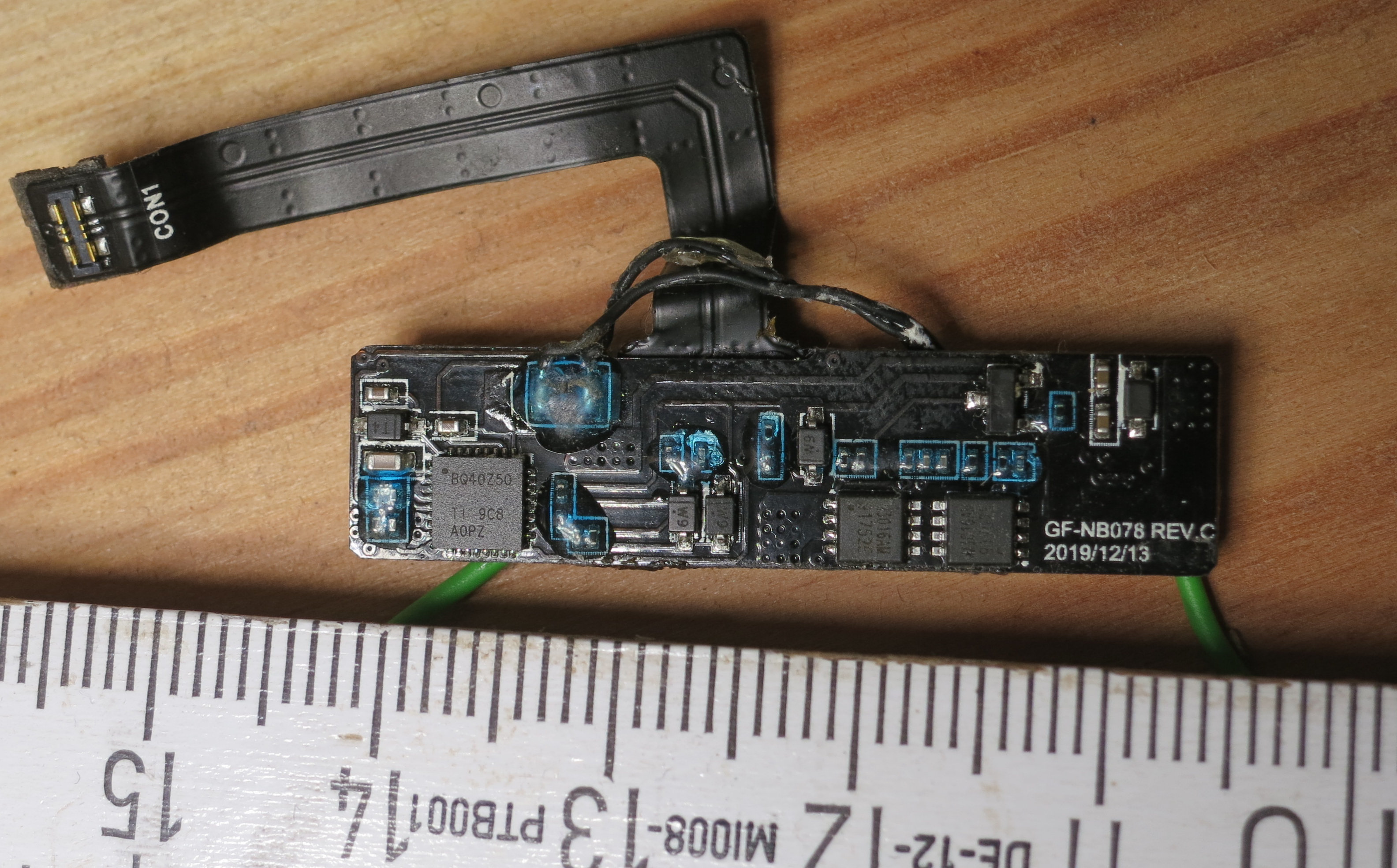
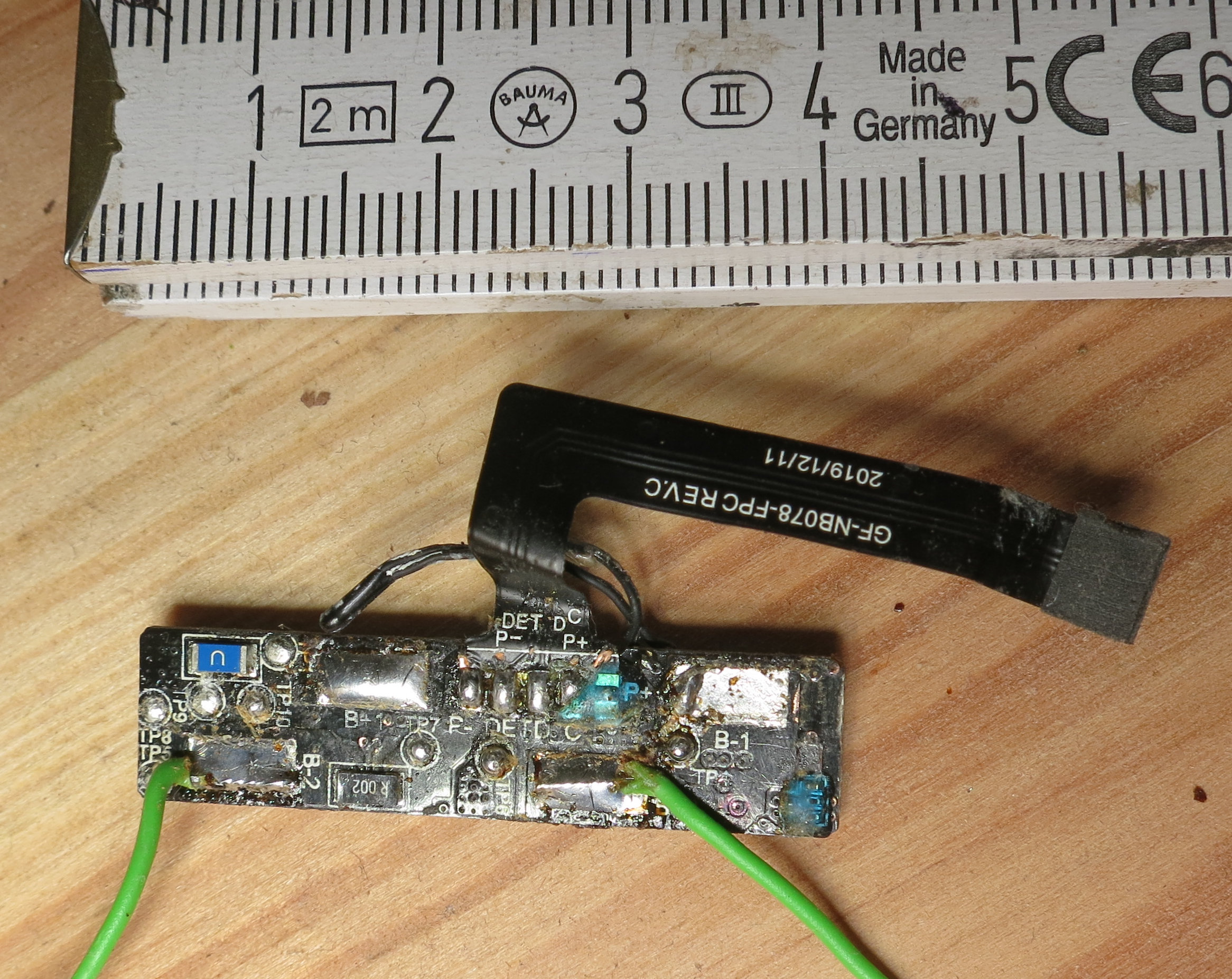
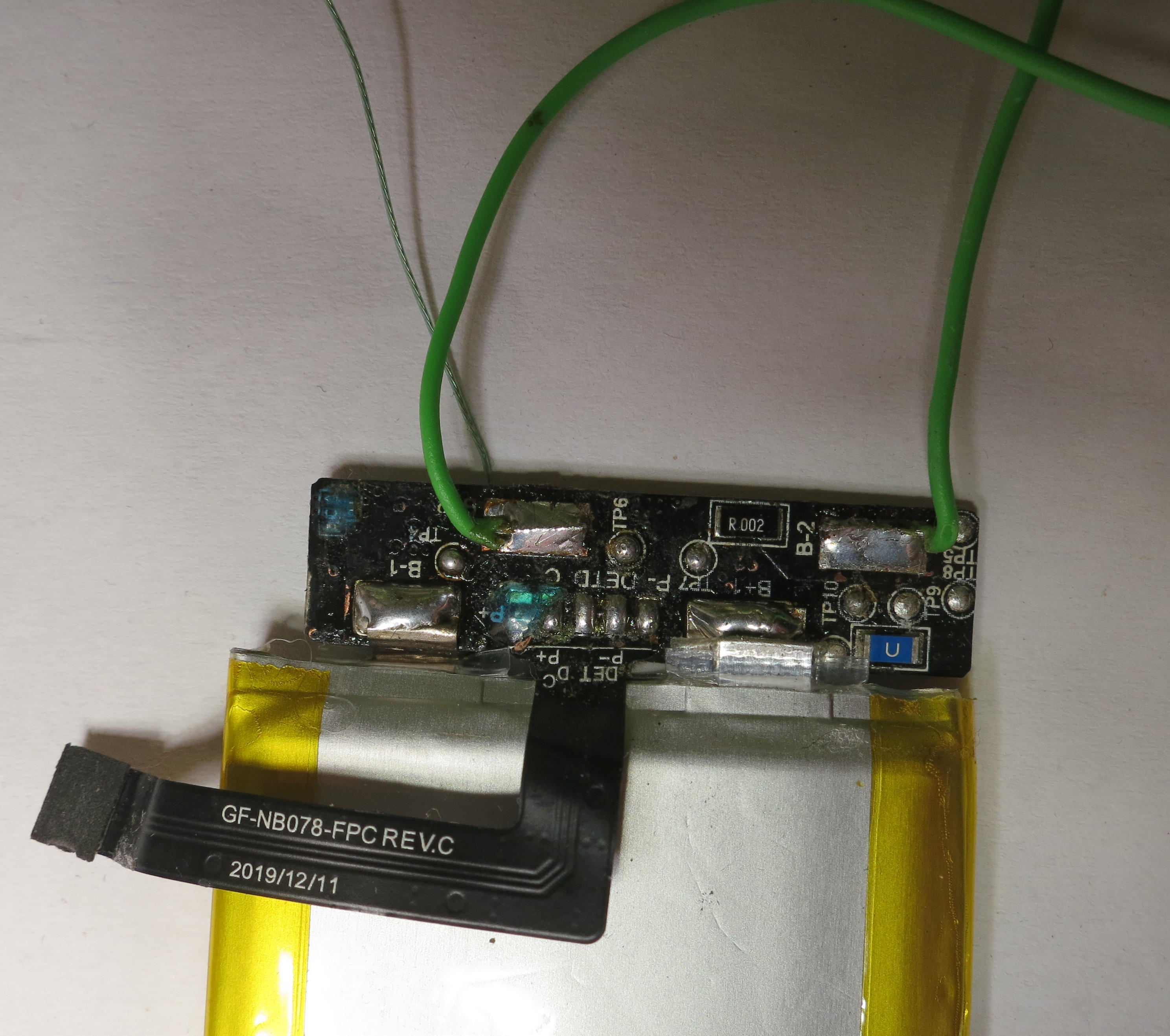
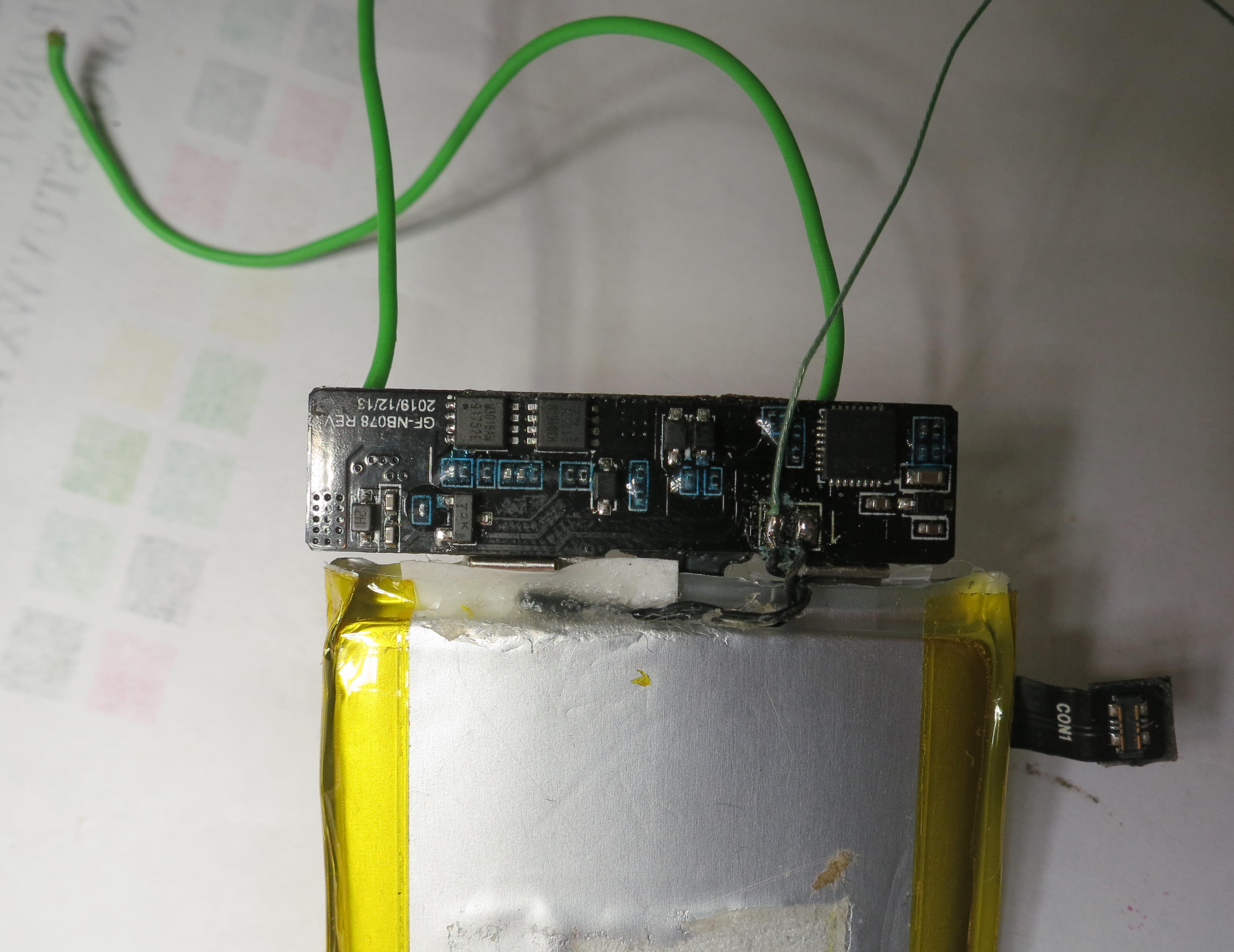
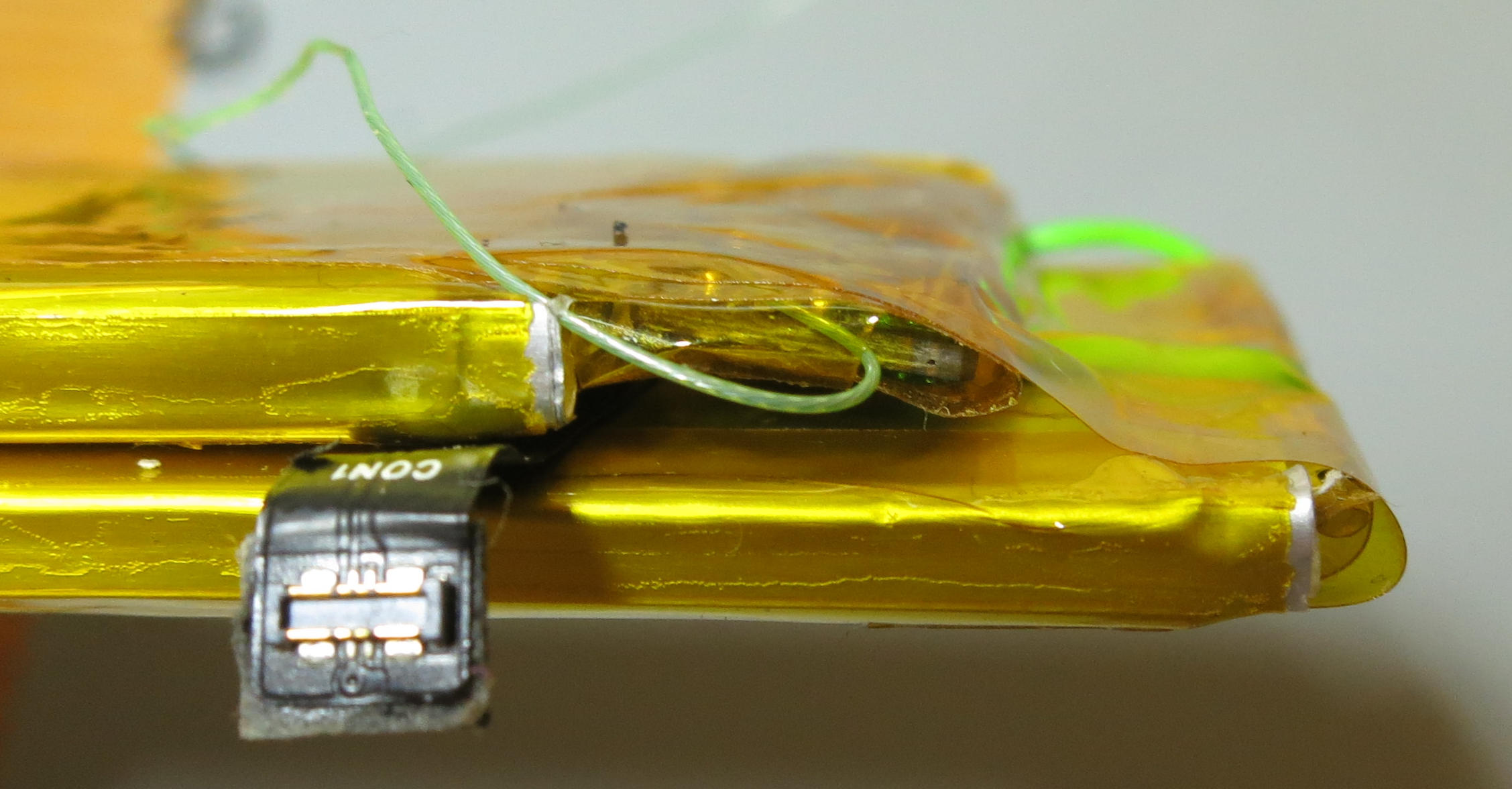
So, to move things around, both cells needed to be desoldered from the electronics board. The board needed to be flipped around, and the top cell has to be attached with short wires.
Desoldering of the cells is possible: Although the battery's contacts are spot-welded, the pieces where they are welded to are soldered flat to the electronics board. They have quite long, folded, electrical connection, so a short soldering should not get the cell too hot.
Also, there was a temperature sensor attached to one of the cells. It also had to be removed and re-attached with some glue. (→ See here for a description where that sensor is leveraged to implement charge control by making the charge controller chip thinking there would be an over temperature condition)
Note that the connector cable from the battery to the main board initially went over both cells, and now has to go between the cells.

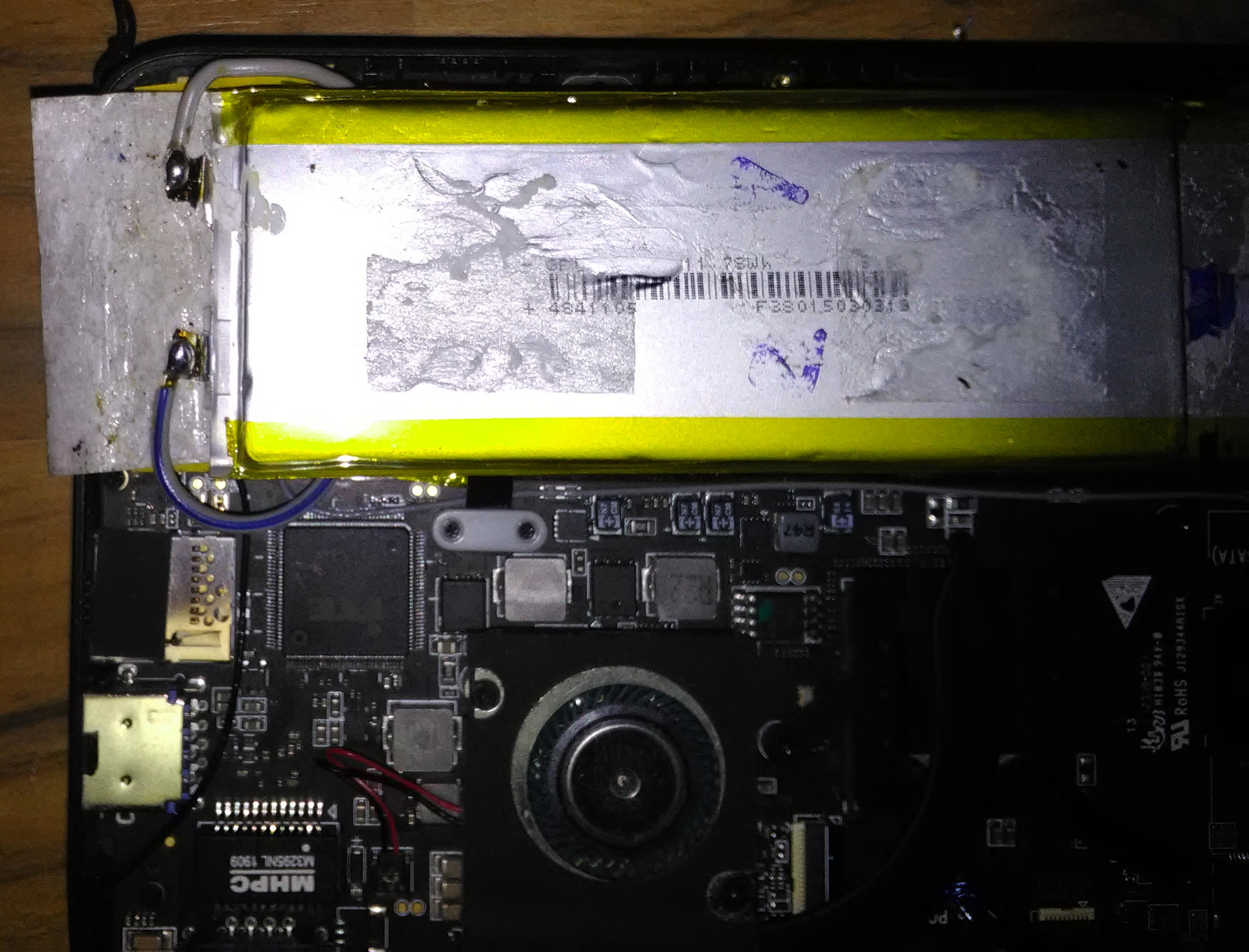
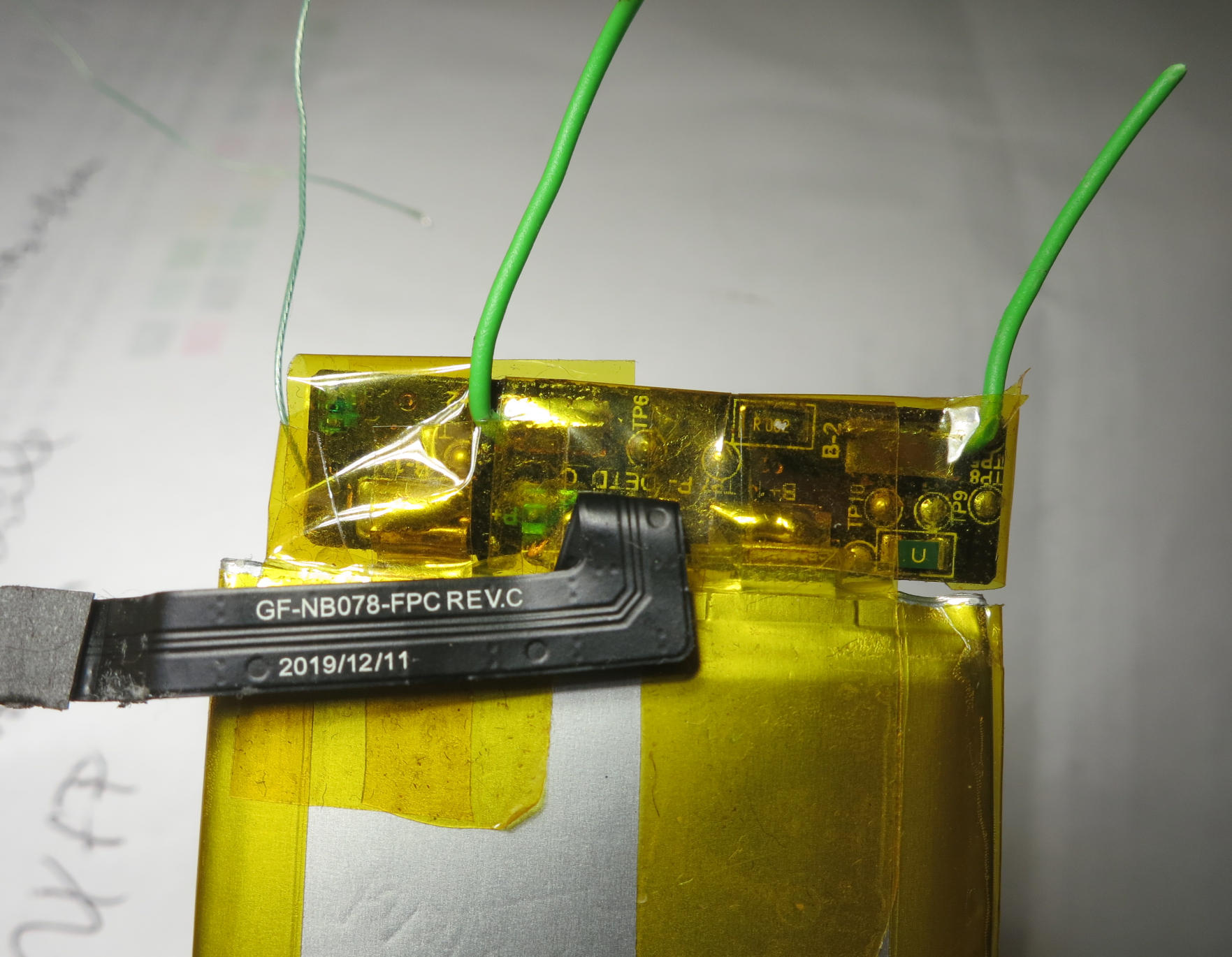
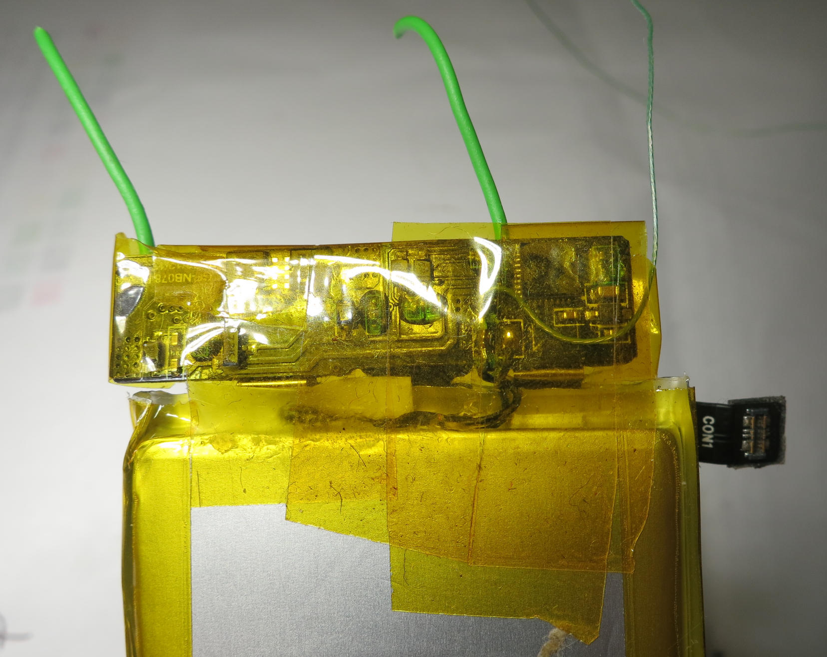
Reassembling the cell, I took care of insulating everything well with kapton tape. For getting the geometry right during reassembling, the easiest was to lay the partly assembled battery pack into the microPC from time to time, thereby taking care not to create any short circuit.
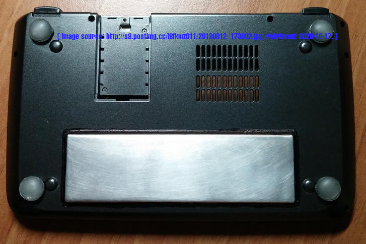
In my first attempt, the whole thing got a bit bulky so that I had to remove some plastic from the lower cover of the MicroPC's case because otherwise it would not close anymore -- the upper cell, which is moved left, had also to be moved a bit more to the front edge of the computer because otherwise it is in the way of the speaker.
In a later attempt that was not needed anymore because I used thinner cables and a better place where to lay the cables.

Now there is space for a 2280 M.2 SSD, I got a 2 TB one. Since the bolt for the 2242 SSD is soldered to the main board, it cannot be removed. So some insulating tape is applied to it to not make a short circuit on the 2280 SSD. After installing the SSD, it is mechanically fixed with some tape, and after closing the case, the case will also help holding stuff in place (small piece of elastic foam applied).

Below are pictures of the process. Note that I first had to find out how to do it and in that process I desoldered both cells. When reattaching them, I had them swapped.

Also, I did not take care in the first place that the connector cable has to go between the cells.

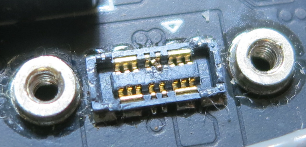
With all the extra work, I might have slightly damaged the battery connector cable: Sometimes the computer does not show any charging or discharging data (although it will still run without power supply) and will also not charge in that cases. Slight force on the cable seems to help out, I‌ need to observe & investigate, and for the next time I now know better.
Update: It turned out that it was due to shortening some data line(s), see below.

GPD MicroPC internals (original), there is only space for a 2242 M.2 SSD. (Image source: gpd.hk.)
(GPD MicroPC internals (original), there is only space for a 2242 M.2 SSD. Image source: GPD, nwzimg.wezhan.hk/contents/sitefiles3601/18006016/images/1361629.jpg, linked from gpd.hk/newsinfo/204174.html, retrieved:‌ 2020-10-17. This image is not by myself.)
GPD MicroPC with the battery cell pack (side view). (Image source: liliputing.com)
(GPD MicroPC with the battery cell pack (side view). Image source: Liliputing, i1.wp.com/liliputing.com/wp-content/uploads/2019/02/open_04.jpg?resize=700%2C373, linked from liliputing.com/2019/02/gpd-micropc-handheld-computer-preview.html, retrieved:‌ 2019-09-02. This image is not by myself.)
GPD MicroPC's battery, cells taken apart. (Image source: ibb.co/86N2QyQ)
(GPD MicroPC's battery, cells taken apart. Image source: Reddit user “ByteOfWood”, i.ibb.co/zGQbt3t/20191127-105120.jpg, linked from reddit.com/r/gpdmicropc/comments/cvb3uk/, retrieved:‌ 2020-10-18. This image is not by myself.)
Battery electronics: Chip side. (Image source: Myself.)
(GPD MicroPC's battery's electronics: Chip side. Image source: Myself.)
Battery electronics: Solder side. (Image source: Myself.)
(GPD MicroPC's battery's electronics: Solder side. Image source: Myself.)
Battery connector. (Image source: Myself.)
(GPD MicroPC's battery's connector. Image source: Myself.)
GPD MicroPC's battery: Lower cell and electronics board. Temperature sensor re-attached from the upper cell to the lower cell (fixed with epoxy glue). (Image source: Myself.)
(GPD MicroPC's battery: Lower cell and electronics board. Temperature sensor re-attached from the upper cell to the lower cell (fixed with epoxy glue). Image source: Myself.)
GPD MicroPC's battery: Lower cell (moved right) and electronics board (with extension cables) fit into the computer. (Image source: Myself.)
(GPD MicroPC's battery: Lower cell (moved right) and electronics board (with extension cables) fit into the computer. Image source: Myself.)
GPD MicroPC's battery: Upper cell (moved left) connected to extension wires. (Image source: Myself.)
(GPD MicroPC's battery: Upper cell (moved left) connected to extension wires. Image source: Myself.)
GPD MicroPC with 2280 M.2 SSD. This shows my second reworked battery with improved cabling and cleaner look. (Image source: Myself.)
(GPD MicroPC with 2280 M.2 SSD. Image source: Myself.)
GPD MicroPC's bottom cover: Plastic needed to be milled away. (Image source: Myself.)
(GPD MicroPC's bottom cover: Plastic needed to be milled away for my first modified battery. Not needed for my second modified battery. Image source: Myself.)
First cell and wires attached. (Image source: Myself.)
Work on my second modified battery with improved cabling and cleaner look. (The extra wire is from this different project to hook onto the temperature sensor to get charge control) Image source: Myself.)
First cell and wires and temperature sensor attached. (Image source: Myself.)
Work on my second modified battery with improved cabling and cleaner look. Image source: Myself.)
Added kapton tape after attaching first cell. (Image source: Myself.)
Work on my second modified battery with improved cabling and cleaner look. Image source: Myself.)
Added kapton tape after attaching first cell. (Image source: Myself.)
Work on my second modified battery with improved cabling and cleaner look. Image source: Myself.)
Testing fit of first cell with PCB. (Image source: Myself.)
Work on my second modified battery with improved cabling and cleaner look: Testing fit of first cell with PCB. Image source: Myself.)
My second modified battery: Finished, side view. (Image source: Myself.)
My second modified battery: Finished, side view. Image source: Myself.)
My second modified battery: Finished, bottom view. (Image source: Myself.)
My second modified battery: Finished, bottom view. Image source: Myself.)

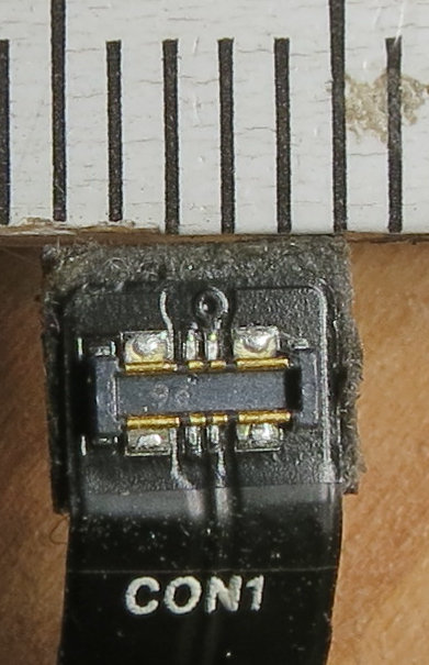
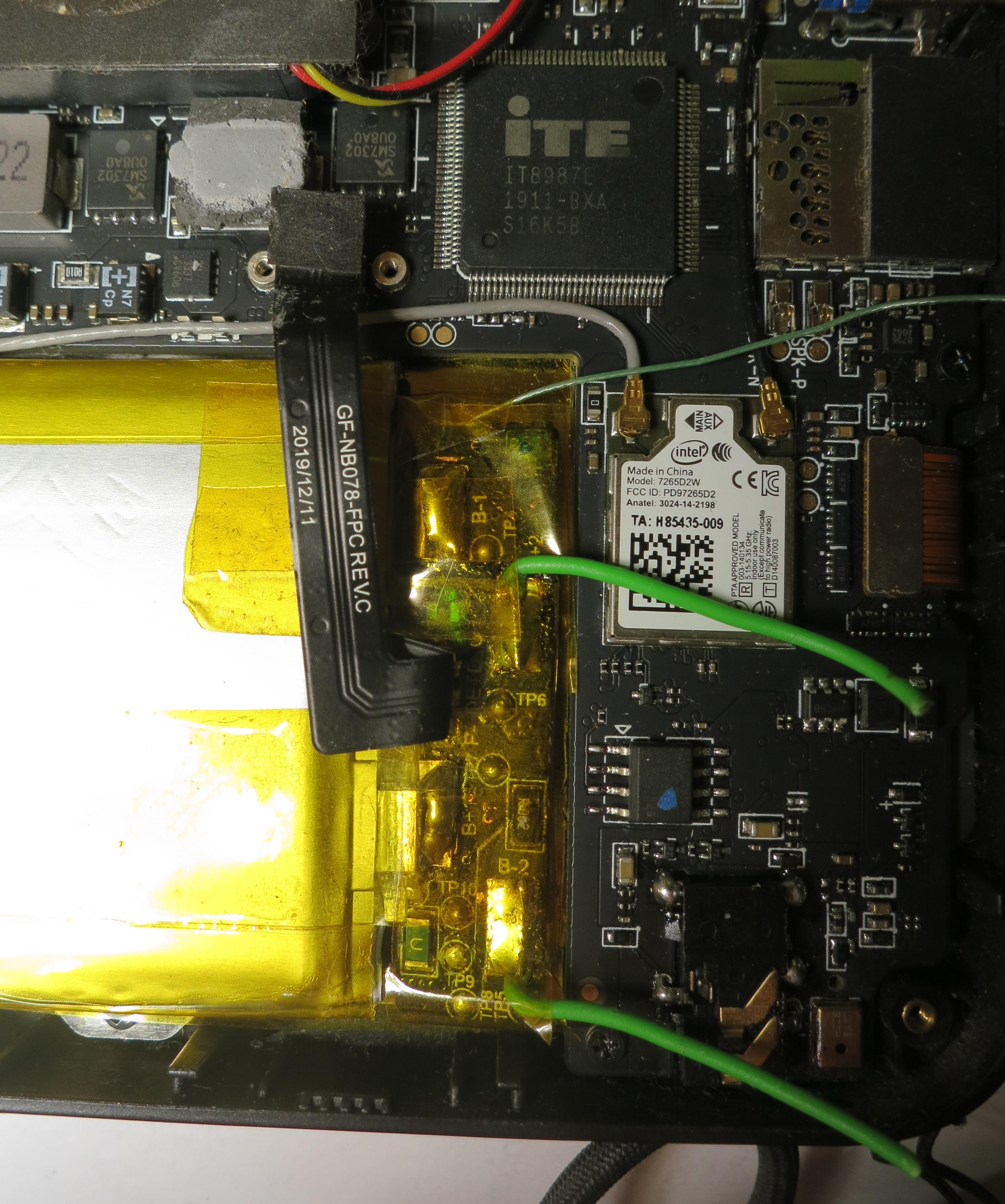
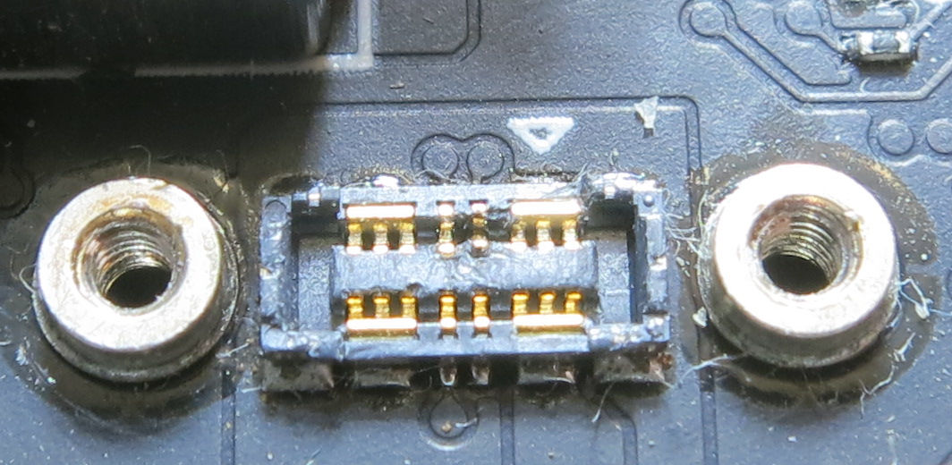
Somehow, the connector on the mainboard got some extra metal piece which got misaligned and caused a data wire to be shortened when the battery cable was properly fastened with pressure, resulting in missing charge state report. It could be fixed:

Battery connector on the mainboard: Data wire shortened. (Image source: Myself.)
(Battery connector on the mainboard: Data wire shortened. Image source: Myself.)
Battery connector on the mainboard: Data wire shortening repaired. (Image source: Myself.)
(Battery connector on the mainboard: Data wire shortening repaired. Image source: Myself.)

Warning and disclaimer.

Only perform such work when you know what you are doing and have some electronics and good soldering proficiency. It is very easy to destroy your battery or even your computer, and risk of fire if you mechanically damage or short circuit or in any other wise mistreat the battery cells or damage the battery electronics board.
I take no responsibility whatsoever for what you do. On this website, I only documented what I did to my very own device. This is not an instruction for others to follow.

Copyright and licensing.


Text-content lastly updated: 2022-03-13, 23:03:56
Page lastly generated: 2023-10-02, 10:51:40