|
.meht ot rotcennoc a hcatta :snip lanretnI <-
351-s2733E iewauH <-
gnikcaH <-
ed.hcurbnettek.scilef
:ereh era uoY
This page has the following sub pages:
|
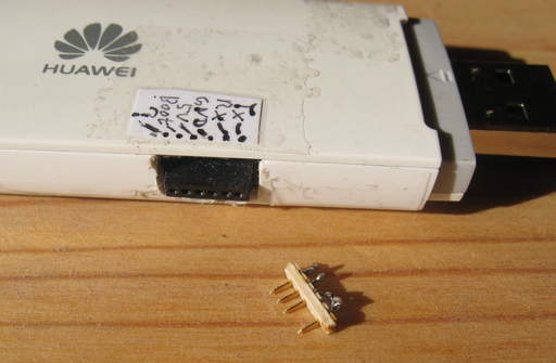
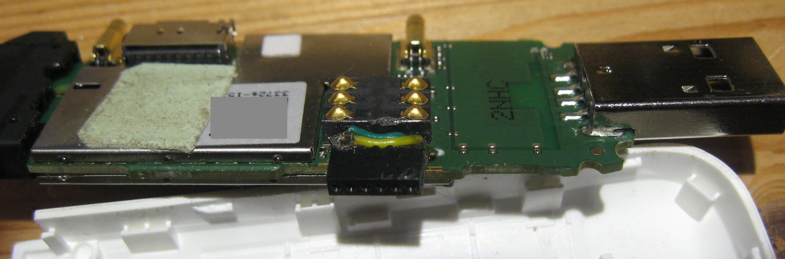
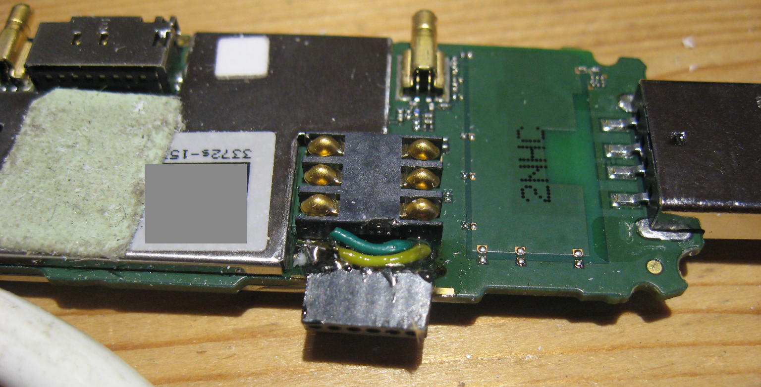
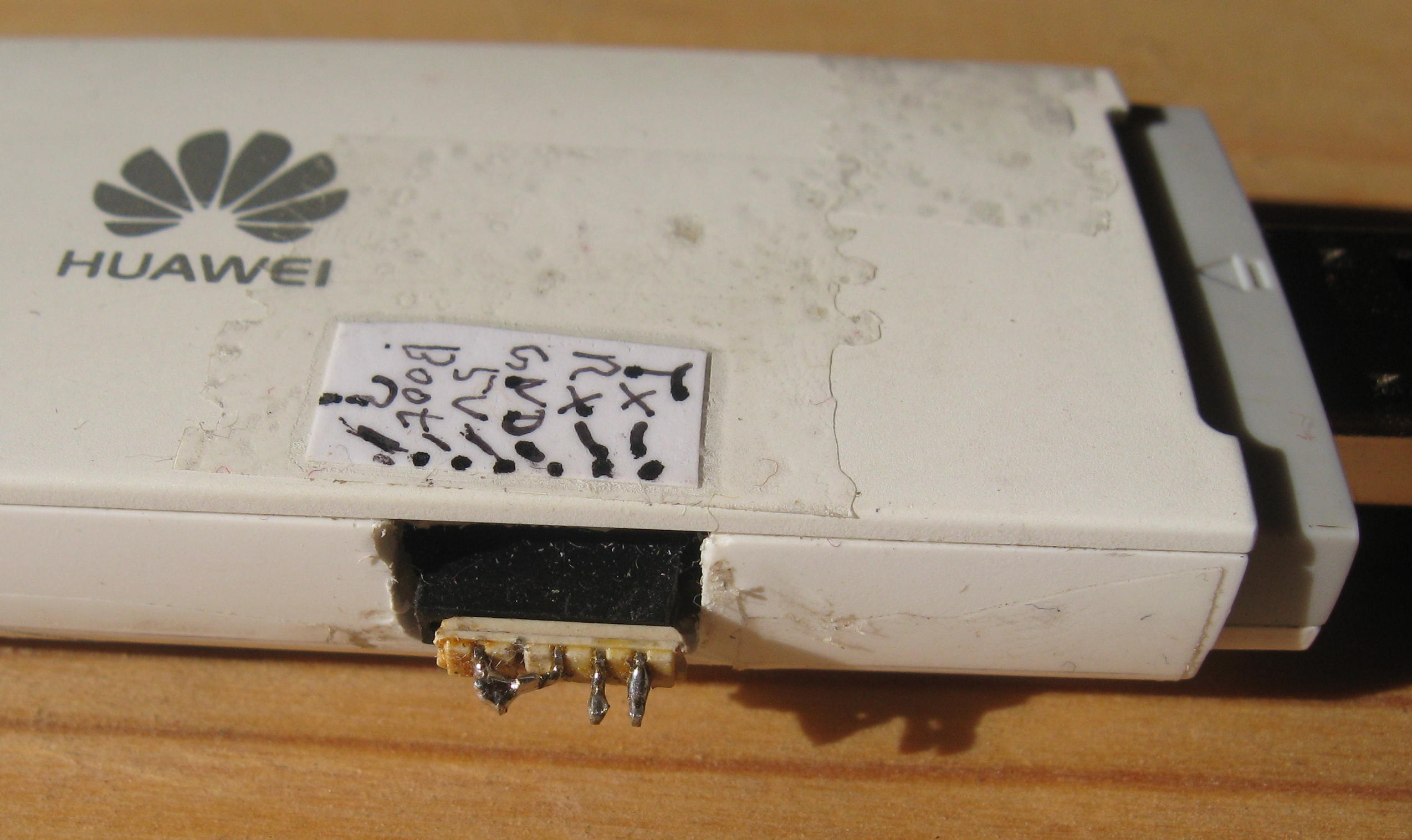
The Huawei E3372s-153 has some internal pins. (The Huawei E3372h-models also have such pins, but they have another layout, see for example this image.)
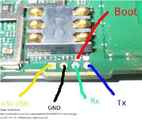
Besides a serial port, a ground pin and a supply-voltage-pin (connected to the +5V-pin of the USB connector), there is also a "boot"-pin and another pin of unknown function.
Shortening the boot pin to ground while powering on the device places the device in special boot loader mode where it provides one serial port over USB where communication with the bootloader is possible.
When in boot loader mode, it is possible to download small images to the device which then enable to flash firmware, bypassing some hassles and checks. A Software to download those small images in boot loader mode is balong-usbdload by "forth32", available in source code (compiles well on GNU/Linux) as well as Windows binaries. After downloading the small binary, the real firmware can be flashed either with the official Huawei firmware update software, or with the software balongflash by "forth32".
Here, I document what I have done with my device. This is not an instruction for others to follow, only a personal documentation. I take no responsibility for what you do to your devices or any harm happening to your devices or computer when you follow what I have done. See disclaimer.
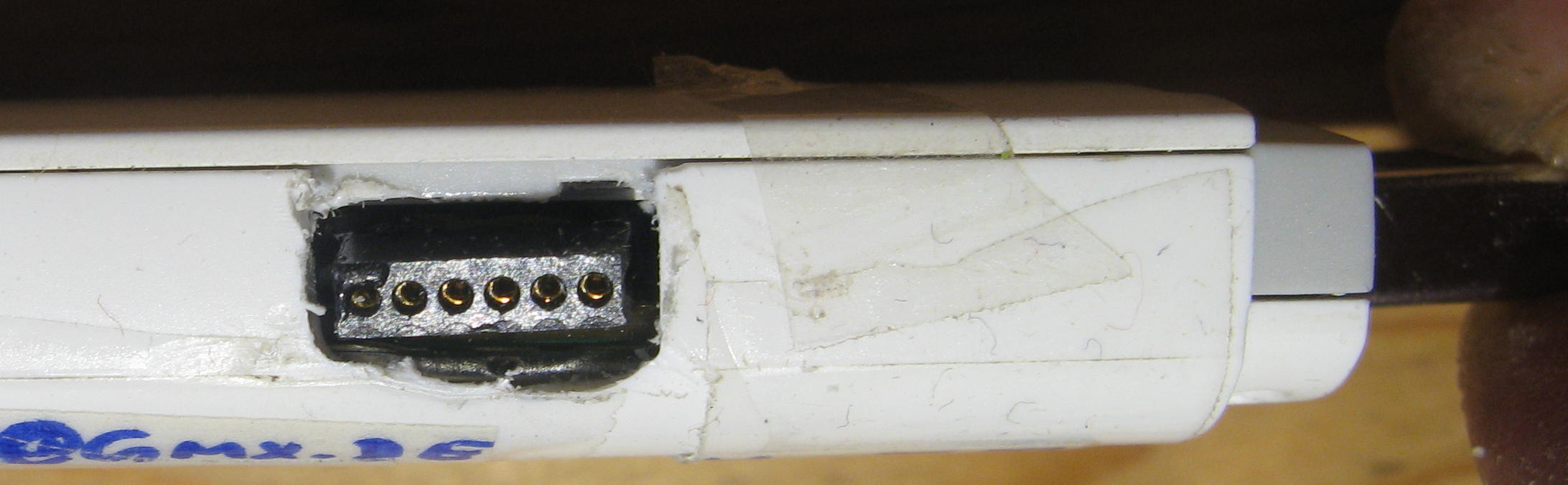
Now, on to the internal pins and making them easily accessible from outside.
For all images which are presented now: Those are only thumbnails; for full size click on them.
Here you can see the internal pins with their function:


Only perform such work when you know what you are doing and have some electronics and soldering proficiency. It is very easy to destroy your device or even your computer, since the USB power supply of the computer is directly connected to the pins I mentioned. A short circuit or an input of wrong voltage can mean the death to the device or the computer.
I take no responsibility whatsoever for what you do. On this website, I only documented what I did to my very own device. This is not an instruction for others to follow.
A good place for information in German about the Huawei E3372-devices is LTE-Forum.at. More general, in Russia there seems to be a good community dealing with those devices, so Russian forums might be even more worth of information.